Matura Thesis on Robotics
Last updated: January 8, 2024
Full Thesis PDF
For a detailed explanation and full documentation of this project, you can view the complete thesis in PDF format by clicking the link below:
View Full Thesis (PDF)
You can also explore the source code and project files on GitHub:
View GitHub Repository
Designing a Microcontroller-Driven Robotic Arm with Software Integration
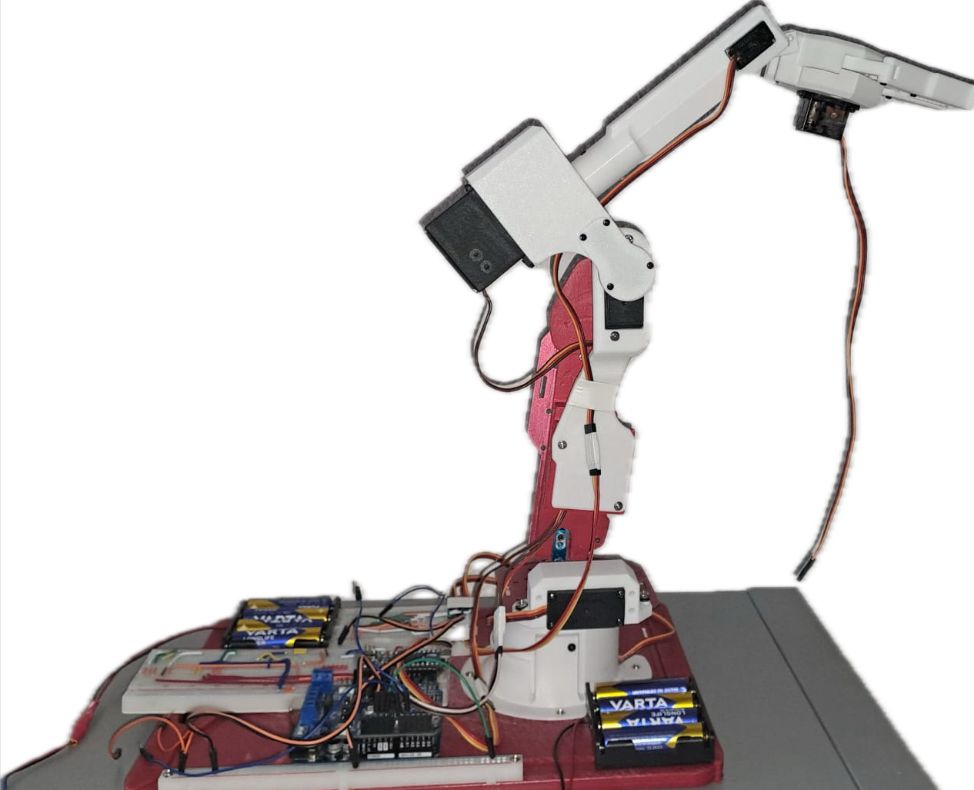
Advanced open-loop control system with six degrees of freedom using servo motors.
This project presents the design and construction of an advanced robotic arm with six degrees of freedom, utilizing servo motors for precise control and positioning. The system focuses on accuracy, strength, and programmability over speed, aiming to replicate the movement and control capabilities of industrial robotic arms using consumer-grade electronics and affordable materials.
Introduction
My fascination with robots and automation began at an early age. The precision and efficiency with which modern industrial robots perform complex tasks have always inspired me. This curiosity motivated me to explore whether I could design and build a robotic system that approaches the performance of these machines, using only components commonly found in hobby kits or easily sourced online.
Objective
The goal of this project was to develop and build a robotic arm with six degrees of freedom—forward/backward, up/down, left/right, yaw, pitch, and roll. The project also included the programming of both approximate and exact control algorithms for maneuverability. The final result is a functional proof of concept demonstrating that complex movement and control capabilities, comparable to those of industrial robot arms, can be achieved using widely available hobbyist components and materials.
Project Overview
This thesis begins with a theoretical background on robotics, discussing the principles behind robot arms, servo motors, and microcontrollers. It then explores the methods used to control the arm, employing both geometric and matrix solutions, including inverse kinematics.
// Example snippet: Calculating forward kinematics
double x = A * cos(theta1) + B * cos(theta2) + C * sin(theta2) + D;
double y = A * sin(theta1) + B * sin(theta2) - C * cos(theta2);
// Example snippet: Calculating joint adjustments using Jacobian matrix
double delta_shoulder = (delta_x * dy_by_elbow - delta_y * dx_by_elbow) / determinant;
double delta_elbow = (delta_y * dx_by_shoulder - delta_x * dy_by_shoulder) / determinant;
Subsequent sections focus on the hardware and software aspects of the project. The hardware chapter details the mechanical design, assembly, and integration of the servo motors, while considering structural strength, weight distribution, and torque requirements. The software chapter presents the control system, with custom-developed inverse and forward kinematics algorithms implemented in C++, enabling precise positioning of the arm within its workspace.
Control System
The robotic arm utilizes an open-loop control system, relying on the inherent positional accuracy of the servo motors without the use of encoders. The core of the system is a custom inverse kinematics (IK) library, which translates desired end-effector positions into precise joint angles.
Mathematical Kinematic Calculations (Trigonometry)

Mathematical Kinematic Calculations (Derivation)
Inverse Kinematics Implementation
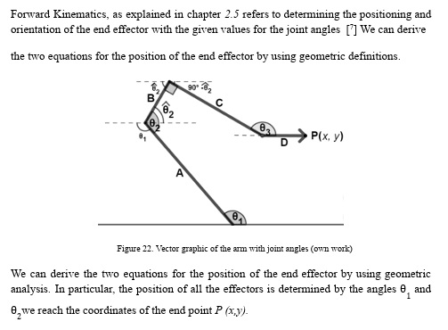
The inverse kinematics approach uses trigonometric principles to calculate joint angles given a target coordinate (x, y). The following code snippet showcases the IK calculation implemented in C++:
// Example: Inverse Kinematics calculation for shoulder and elbow joints
double R = sqrt(pow((x - D), 2) + pow(y, 2));
double S = sqrt(pow(B, 2) + pow(C, 2));

double shoulder_angle = acosDegrees((x - D)/R)
  + acosDegrees((pow(A, 2) + pow(R, 2) - pow(S, 2)) / (2 * A * R));

double elbow_angle = acosDegrees(B/S)
  + acosDegrees((pow(S, 2) + pow(A, 2) - pow(R, 2)) / (2 * A * S));
Derivative Method for Real-Time Adjustments
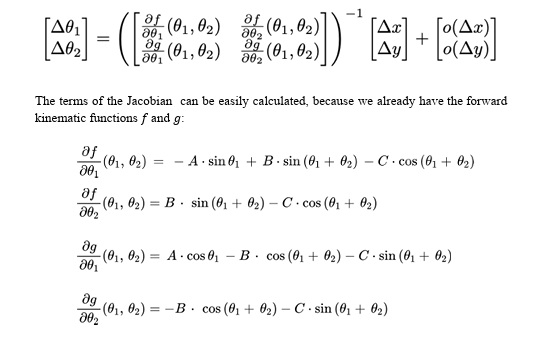
For real-time movement adjustments, a derivative-based approach was implemented, utilizing the Jacobian matrix to estimate the required angular changes for a small positional increment:
// Example: Calculating angle changes using the Jacobian matrix
double delta_shoulder_angle = (
  delta_x * dy_by_elbow_angle - delta_y * dx_by_elbow_angle) / determinant;

double delta_elbow_angle = (
  delta_y * dx_by_shoulder_angle - delta_x * dy_by_shoulder_angle) / determinant;
Control Loop and Input Device
An analog joystick serves as the input device, providing intuitive control over the arm’s motion. The control loop reads the joystick inputs and maps them to Cartesian deltas, which are then processed by the selected control algorithm.
// Example: Reading joystick input and commanding movement
int joystickX = analogRead(A0);
int joystickY = analogRead(A1);

double delta_x = map(joystickX, 0, 1023, -5, 5);
double delta_y = map(joystickY, 0, 1023, -5, 5);

robot.moveBy(delta_x, delta_y);
Finally, the project concludes with testing protocols to evaluate the system’s performance, including trajectory following, accuracy, repeatability, and endurance tests. The results are analyzed and compared to both industrial and hobbyist robotic systems, and reflections on the project’s limitations, possible improvements, and learning outcomes are provided.
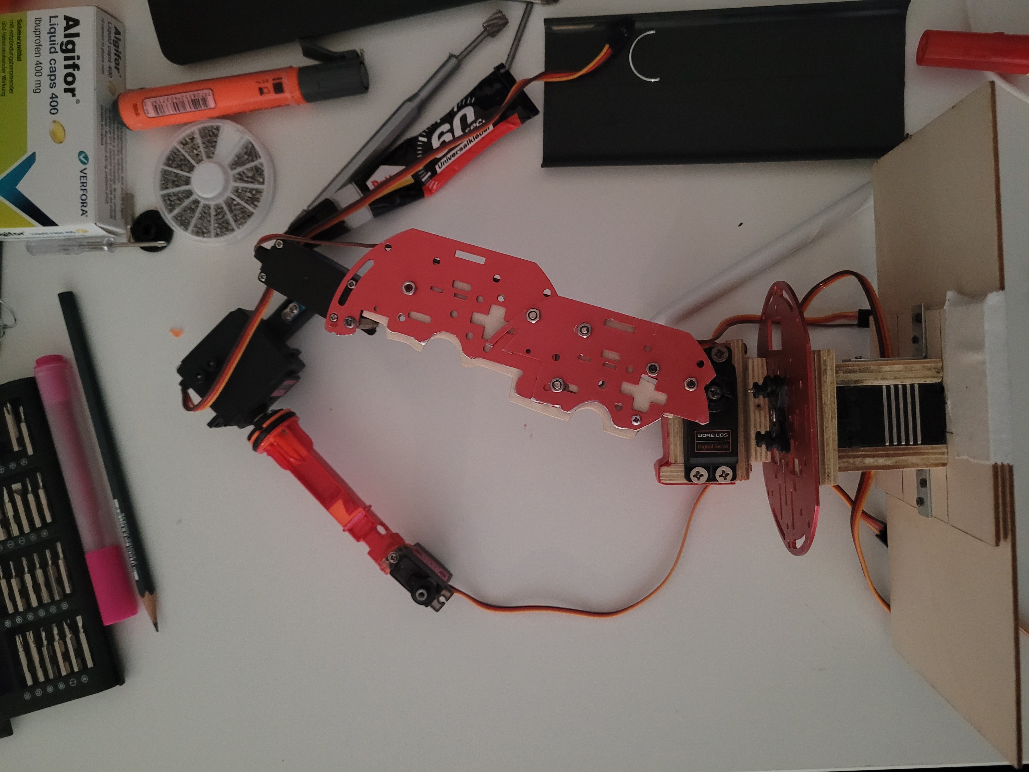
Mechanical Build
Vertical Movement with Kinematics
Full Thesis PDF
For a detailed explanation and full documentation of this project, you can view the complete thesis in PDF format by clicking the link below:
View Full Thesis (PDF)
You can also explore the source code and project files on GitHub: