6-DOF Stepper Robot arm
Last updated: May 5, 2025
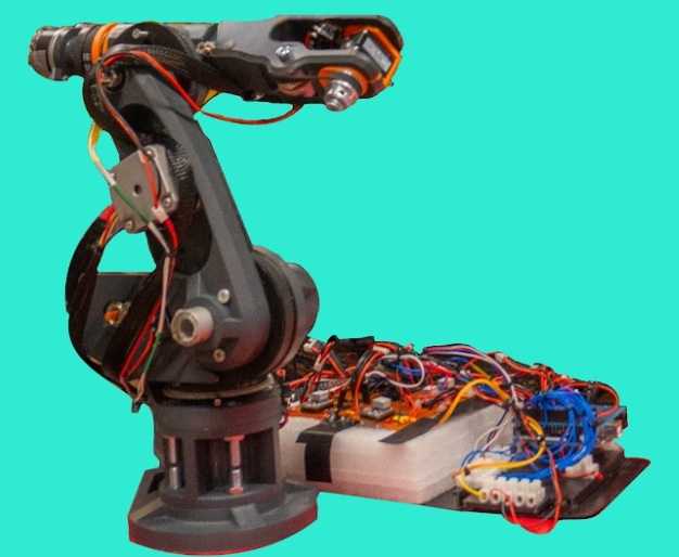
Advanced open-loop control system with six degrees of freedom using stepper motors.
This project is an advanced robotic arm with six degrees of freedom using stepper motors for precise control and positioning. The design prioritizes accuracy, strength, and programmability over speed, making it ideal for tasks that require exact positioning.
Motivation for this project was seeing the project files and mechanical design being open source and 3-D printable. I made some personal modifications, since I dont have acces to a CNC machine, so the arm is *entirely printable
*exeptions being mechanical components like pulley, belts and screws.
Technical Specifications
- Motors: NEMA 17 stepper motors (base, shoulder, elbow) and NEMA 14 (wrist), Nema 11 (hand)
- Controllers: TMC2209 stepper drivers for quiet operation
- Microcontroller: Arduino Mega 2560
- Power Supply: 14V 10A power supply
- Structure: 3D printed components (PLA+), 15mm Aluminium tube
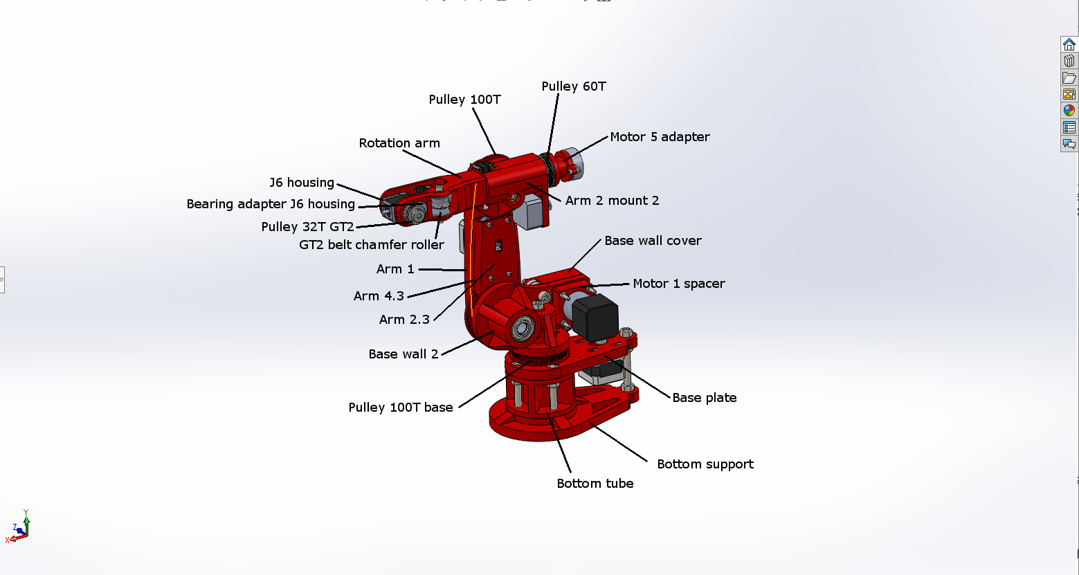
3D-printable components:
:https://drive.google.com/drive/folders/18V6IwFhVz9q9WkO90WXbbdgPHuDpX7gw?usp=sharing
folders: (stand/Arm1/Arm2/Base) for the stl files.
Hardware components
Steppers:
- From www.omc-stepperonline.com models:
- 17HS13-0404S-PG5 (Nema 17 with 5:1 planetary gearbox)
- 14HR05-0504S (Round Nema 14 7Ncm)
- 14HS08-0404S (Nema 14 5Ncm)
- 17HS16-2004S1 (Nema 17 45Ncm)
- From banggood.com:
- Nema 17 (https://www.banggood.com/42mm-12V-Nema-17-Two-Phase-Stepper-Motor-For-3D-Printer-p-1164619.html?rmmds=myorder&cur_warehouse=CN)
- Nema 8 (https://www.banggood.com/JKM-NEMA8-1_820-Hybrid-Stepper-Motor-Two-Phase-30mm-Motor-For-CNC-Mill-Router-p-980604.html?rmmds=myorder&cur_warehouse=CN)
- Limit switches:
- https://www.banggood.com/10Pcs-Micro-Limit-Switch-Roller-Lever-5A-125V-Open-Close-Switch-p-945733.html?rmmds=myorder&cur_warehouse=CN
- Pulleys and belts:
- GT2 16tooth (4pcs)
- GT2 16tooth timing pulley - without tooth (2pcs)
- GT2 6mm closed loop belts (280mm 2pcs, 200mm 1pcs, 158mm 1pcs)
- HTD3 16T pulley
- HTD3 closed belt 330mm
- Bearings:
- 608 8x22x7 (2pcs)
- 625 5x16x5 (4pcs)
- 6002 15x32x9 (4pcs)
- 20X35X10 axial ball bearing (1pcs, originally used 2 but only needs one between stand and base)
- Bunch of nuts and bolts mainly m3 and m4 hex head (M8 bolts on the stand, base (for HTD3 tensioner bearings) and Arm2 mount)
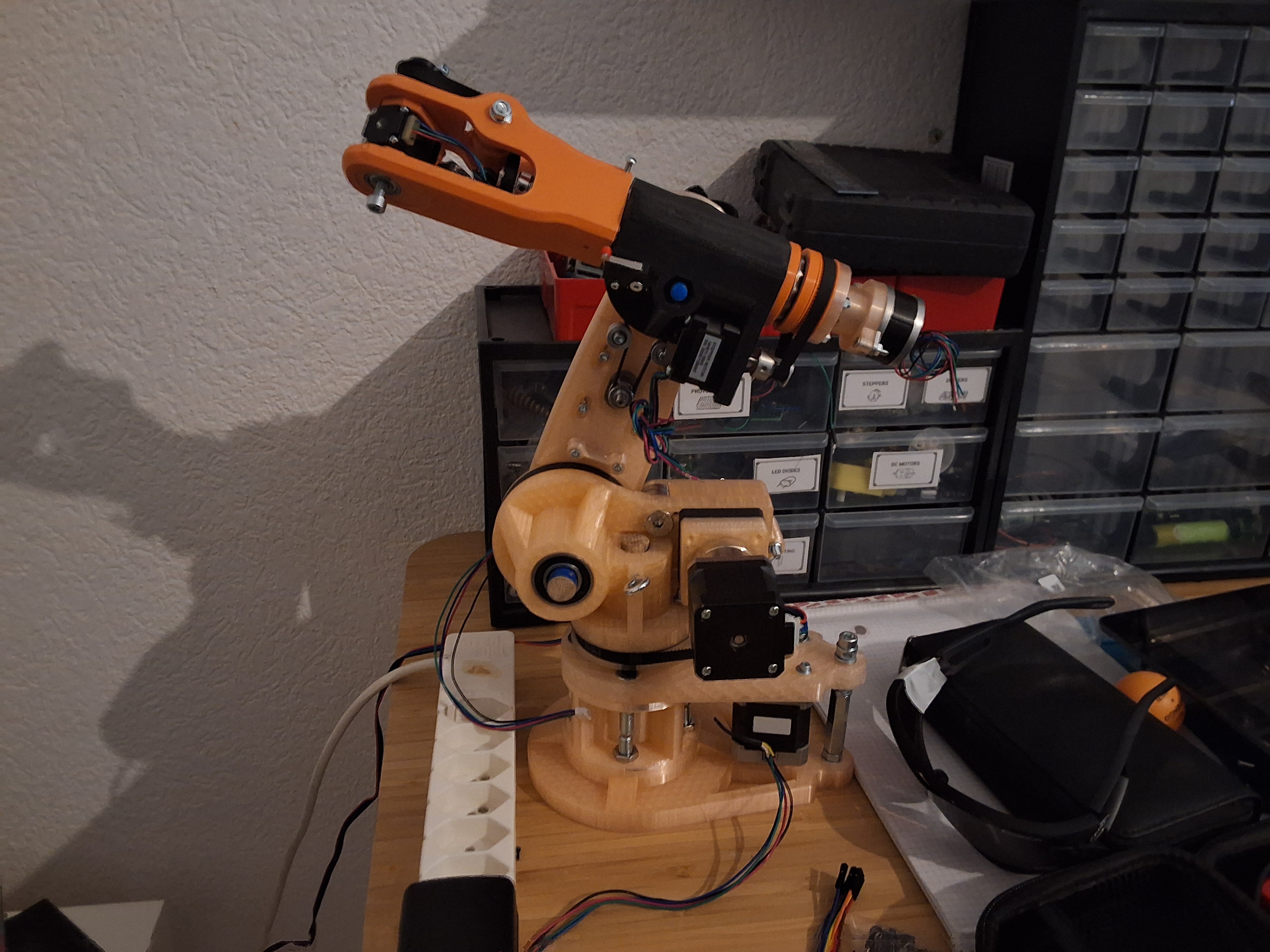
Assembly video:
Final Assembly :
Control System
Stepper motors controlled with TMC2209 drivers, Step and Dir pins. A0-A5 pins for Limit switch signal. Arduino code handles the homing of the motors and callibration. Because we know the stepper resolution, microstep setting and gear reduction, we can talk in degrees after, instead of steps.
else if (inData == "autohome") {
    Serial.println(F("=== STARTING AUTO CALIBRATION & HOMING ==="));
    bool allSuccess = true;

    // Joint 0: Calibrate, move to home, set home
    Serial.println(F("\n--- Auto Homing Joint 0 ---"));
    if(findLimitSwitch(0)) {
      Serial.println(F("Moving J0 to home position..."));
      moveStepperSteps(0, -3800);
      currentSteps[0] = 0;
      currentAngles[0] = 0;
      homeSet[0] = true;
      limitFound[0] = true;
      Serial.println(F("Joint 0 homed!"));
    } else {
      Serial.println(F("Joint 0 calibration failed!"));
      allSuccess = false;
    }
angle movement instead of steps:
void moveJointToAngle(int joint, float angle) {
  long targetSteps = (long)(angle * STEPS_PER_DEGREE[joint]);
  long stepsToMove = targetSteps - currentSteps[joint];
  moveStepperSteps(joint, stepsToMove);
}
After the callibration, we move the robot to its home position:
else if (inData.startsWith("home")) {
    int jointNum = inData.substring(4).toInt();
    if(jointNum >= 0 && jointNum < NUM_JOINTS) {
      if(!limitFound[jointNum]) {
        Serial.println(F("Find limit first"));
        return;
      }

      currentSteps[jointNum] = 0;
      currentAngles[jointNum] = 0;
      homeSet[jointNum] = true;

      Serial.print(F("Home set for joint "));
      Serial.println(jointNum);

      // Check if all calibrated
      bool allCalibrated = true;
      for(int i = 0; i < NUM_JOINTS; i++) {
        if(!homeSet[i]) allCalibrated = false;
      }
      if(allCalibrated) {
        isCalibrated = true;
        Serial.println(F("*** ALL JOINTS CALIBRATED - IMU CONTROL READY ***"));
      }
    }
  }
.PNG)
Robot home position. (inverted L)
For my end project submission, I presented my implementation of the STM32 discovery kit as a joystick. I read the gyroscope and magnetometer data and used Sensor Fusion to display accurate Tilt data as a 3D pygame render. The board’s tilt then corresponded with joint movement (forward tilt made J1 rotate forward, etc…)
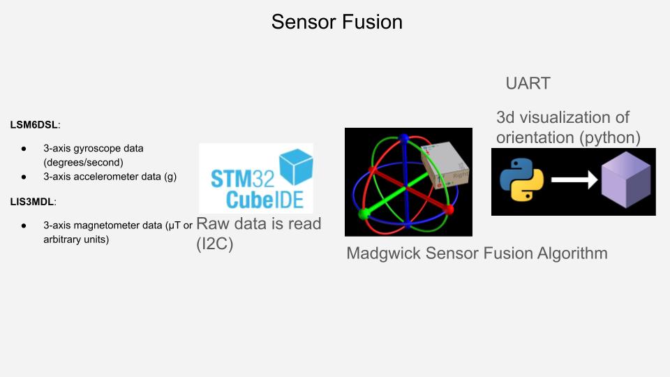
Data is read from the LSM6DSL and LIS3MDL sensors and fed into the madgwick sensor fusion algorithim. This improved sensor data is then visualized on python using a script running pygame:
Pygame visualisation:
.jpg)
Here you can see the Rotation and Tilt of the board. When the tilt is above a threshhold, a direction is noticed and a signal is sent via serial to the arduino to make the corresponding movement.
Project Workflow:
.jpg)
STM32 board on the left, feeding sensor data to the C programm, which has the Madgwick alg, which then sends the data to python for display. The python script detects tilt, sends serial orders to the arduino which effects movement on the steppers.
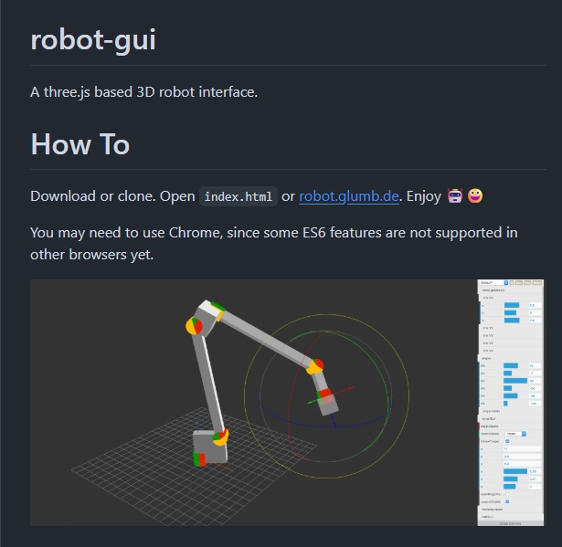
Future plans for the robot:
- Fork the Robot-Gui from maximillian beck and implement keyboard control, and serial data communication to the arduino so I can use coordinate control.
- Chess Playing bot
.jpeg)